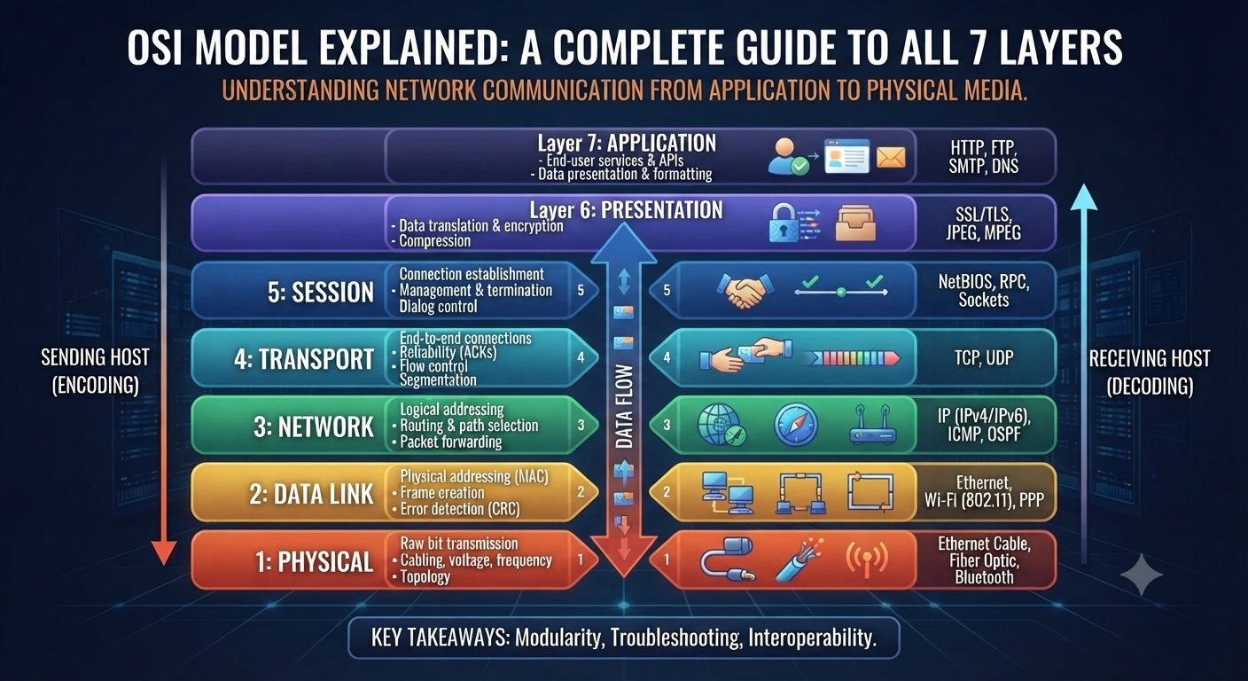
The OSI Model Explained: A Complete Guide to the 7 Layers If you have started learning networking, then you would have heard about the OSI Model within the first few days. You’ll see it in every textbook, on every certification exam, and in almost every networking interview question. And with good reason: it’s the most useful mental model for understanding how data actually travels from one device to another. In this guide we’ll walk through this framework one layer at a time, explain why it still matters even though real-world networks don’t follow it exactly, and show you how to actually remember all seven layers without just memorizing a list. The OSI model is the Open Systems Interconnection model. The OSI Model, which stands for Open Systems Interconnection Model, is a conceptual model that standardizes the way in which various network protocols communicate and interact with one another. It breaks the whole process of network communication into 7 different layers . Each layer has a specific job . Think of it like a mail system . A letter passes through several stages before it arrives at its destination: it is written, put in an envelope, addressed, sorted and delivered. This is the same idea as the framework, except instead of a letter you have data moving across a network, and instead of a mail carrier each layer passes the data to the next. The International Organization for Standardization (ISO) developed it to give network engineers a common language and standard way to design and troubleshoot systems, no matter the vendor or technology used. Why the OSI Model Still Matters Today Some students ask why they need to learn this framework, since real networks run on the simpler four-layer TCP/IP model. This is why it still deserves a place in every curriculum: It is the standard troubleshooting framework. When something goes wrong, network engineers will ask, “which layer is this happening at,” and that question alone quickly identifies the issue. It establishes a common language. It is this model that makes sense of terms like “Layer 2 switch” or “Layer 3 routing.” Engineers all over the world use the same reference points. It’s on all the major certifications. CCNA, Network+ and nearly every other entry-level IT exam tests your knowledge of it directly. It simplifies a very complicated thing. It’s much easier to learn than trying to understand everything at once when you break down the network communication to 7 more manageable parts. Although real hardware and software do not break down into exactly seven discrete layers, this model is still the best teaching tool in the industry for understanding how networks work. Understanding the 7 Layers of the OSI Model As data is sent, it passes down through the layers. As data is received, it passes back up through the layers. Lets look at each layer from the one closest to the user. Layer 7 Application Layer This is the layer you actually work with. It includes the protocols that permit applications to communicate over a network, such as HTTP (web browsing), FTP (file transfers), and SMTP (email). This is the layer you are working at when you open a browser and load a website. Layer 6: The Presentation Layer This layer handles formatting, encryption, and compression so that data sent by one system is correctly understood by another. Basically it converts the data to a format that both sender and receiver understand . It also does some other stuff like SSL/TLS encryption . Layer 5: Session Layer It is responsible for the establishment, management and closure of communication sessions between two devices. It keeps track of whose turn it is to send data. It keeps sessions in sync, which is very important for things like video calls and long file transfers. Layer 4: Transport Layer This is where the data is reliably delivered. TCP and UDP are live protocols here. TCP ensures data arrives in the right order, but UDP sacrifices this guarantee for speed, which is why it’s used for live streaming and online gaming. Layer 3 Network Layer The Network Layer takes care of logical addressing and routing . It finds the best path for data to travel through multiple networks . It is responsible for getting data from one network to another . At this layer IP addresses and routers are used . Layer 2: Data Link Layer This layer is responsible for formatting data for transmission, and detecting errors, between two directly connected devices. MAC addresses and switches are found here and this layer is also where Ethernet frames are created. Layer 1: The Physical Layer Here’s the groundwork: real cables, network adapters, radio frequencies, electrical signals. This is simply the transmission of bits, ones and zeroes, over a physical medium. Remembering the Layers of the OSI Model Most students use a mnemonic to cement the order in memory. One popular one going down from Layer 7 to Layer 1 is: “All People Seem To Need Data Processing” All = Application People = Presentation seem = session To = Transport Need = Network DataLink = Data Processing = Physical Choose your own poison or make your own. Whatever floats your boat. The exact wording of the mnemonic is much less important than the order. OSI Model vs TCP/IP Model: Significant Differences A lot of beginners get confused between these two so here is a clear side by side comparison. Factor TCP/IP Model This Framework Number of layers 4 layers 7 layers Origin ISO theoretical standard development Developed by the U.S. Department of Defense, based on actual protocols Usage Instruction and Troubleshooting Guide What real-world networks actually run Application, Presentation, Session Equivalent to Layer 7-5 Combined into a single Application layer Equivalent to Layer 4 Transport Transportation Equivalent of Layer 3 Network Internet Layer 2-1 equivalent Data Link, Physical Combined into one Network Access layer Real World Examples of OSI Model Knowing the layers in theory is one thing.